Basic RF characteristics and modulation
Very basic RF characteristics everybody should know and how they are used in modulation
Frequency, wavelength, amplitude, and phase
In the previous article we already mentioned the terms frequency and wavelength of an RF wave (actually not only RF, but as we are interested in RF and Wi-Fi, we will always talk about RF waves). Both are connected by the formulas
where is frequency, is the wave’s propagation speed, and is wavelength. For electromagnetic waves in a vacuum, is the speed of light, . Textbooks often use this value to simplify calculations, and we will do the same here. In other media, electromagnetic waves propagate more slowly.
One direct implication is that the higher the frequency, the shorter the wavelength.
In Wi-Fi networks, the devices operate in frequency ranges: sub-1 GHz, 2.4 GHz, 5 GHz, 6 GHz and 60 GHz, while mostly used are 2.4 GHz and 5 GHz nowadays.
Using the formula above, and knowing that hertz describes the number of cycles per second, we can calculate that an RF wave at 2.4 GHz has a wavelength of roughly
and in the 5 GHz bands the wavelength is approximately 6 cm. Of course in each band the frequency is slightly different and therefore the wavelength is also different.
To imagine frequency and wavelength, think of a stone which was thrown into a lake. At the place where the stone entered the water a wave starts to spread in all directions. Now, just imagine that this stone hits the water periodically and each time a new wave is generated. This periodicity corresponds to the frequency and the distance between two waves is the wavelength. Of course, these waves are not RF waves but this is good enough for visualization.
Mathematically, the easiest way is to imagine that we have a pure radio wave:
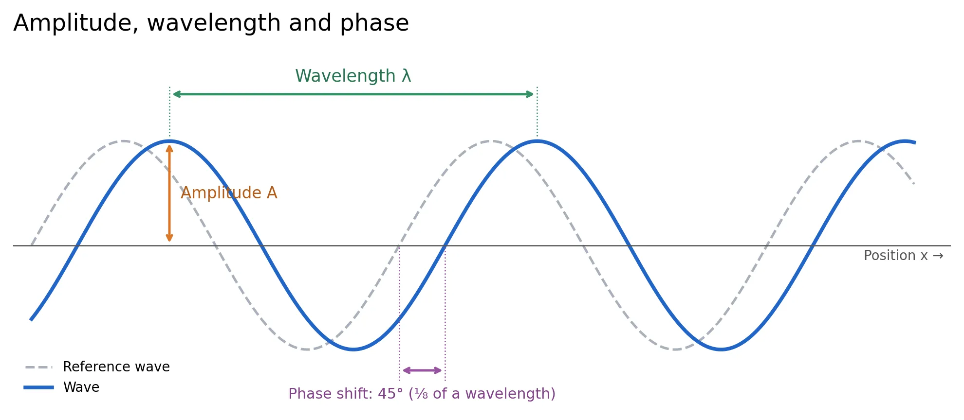
This formula shows the three properties we can manipulate:
- Amplitude (): the wave’s peak magnitude
- Frequency (): how quickly it oscillates
- Phase (): shift along the x-axis
The following image shows these characteristics:
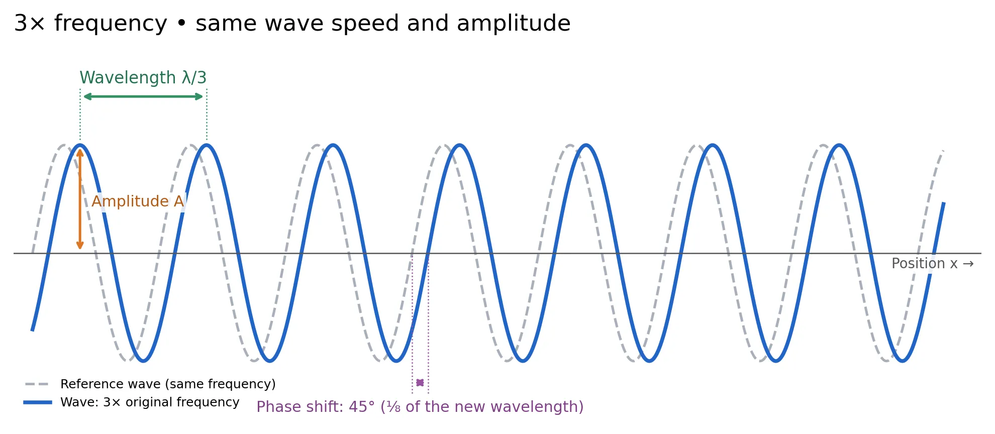
The next image shows a wave with three times the frequency:
Modulation
These three properties become useful when we want to transfer information from a transmitter to a receiver using RF waves. A transmitter varies one or more properties of a carrier wave, and a receiver detects those variations. The following sections give a simplified explanation of how this modulation can carry user data.
Amplitude modulation—change the “strength”
Imagine:
- 0 → small amplitude
- 1 → large amplitude
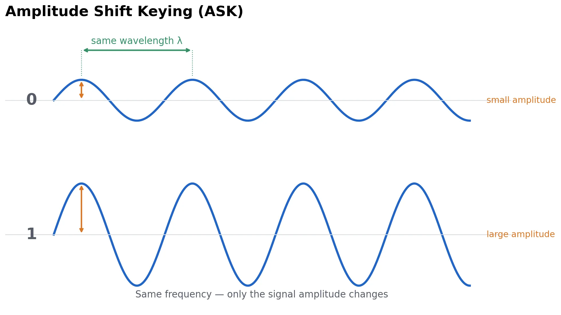
The frequency stays the same, but the signal strength changes. For digital communication, this concept is called ASK — Amplitude Shift Keying.
However, the problem is that amplitude is easily affected by interference, attenuation, obstacles, etc., so using amplitude alone isn’t particularly robust.
Frequency modulation—change the “oscillation speed”
Now keep the amplitude approximately constant but change the frequency.
So we could define:
- low frequency = 0
- high frequency = 1
This is FSK — Frequency Shift Keying.
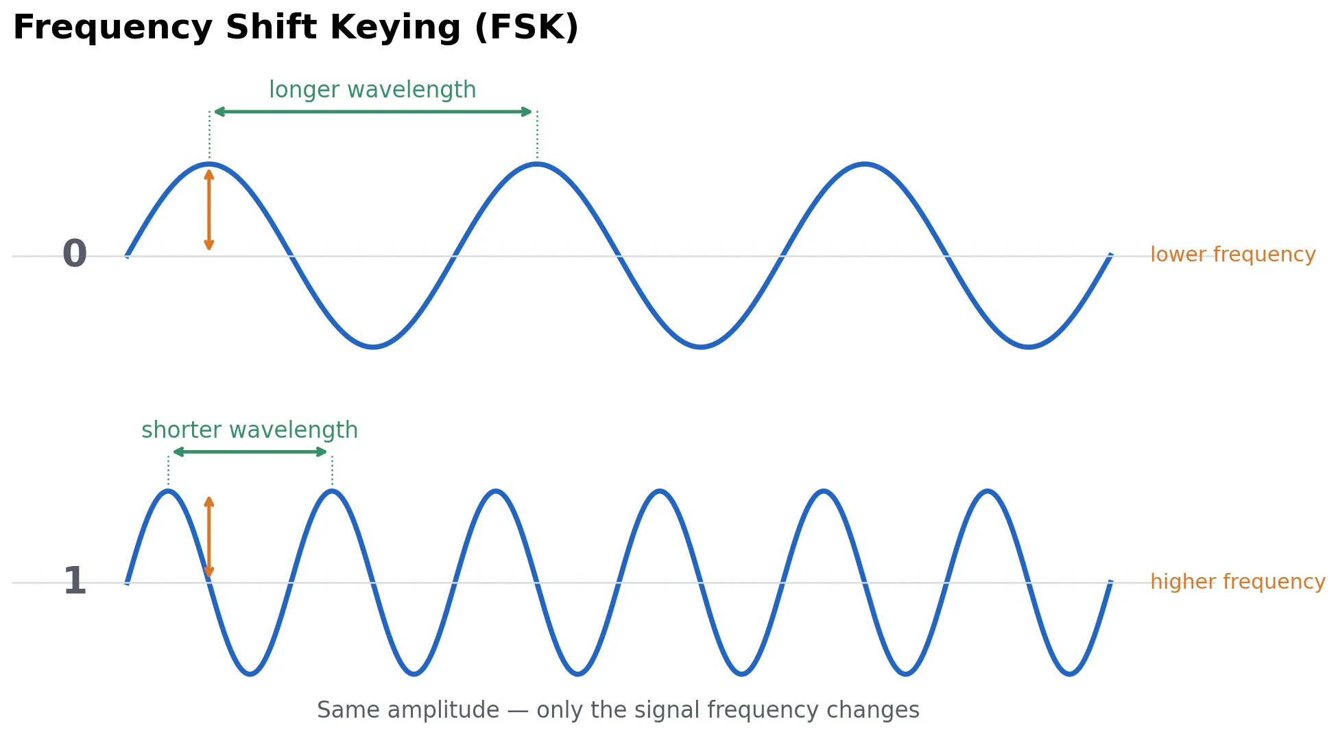
The important point is that we don’t necessarily jump from something like 2.4 GHz to 5 GHz. We make relatively small frequency shifts around the operating frequency.
Phase modulation—shift the wave
This one is initially less intuitive.
Imagine that the transmitter and receiver know how the wave is expected to continue:
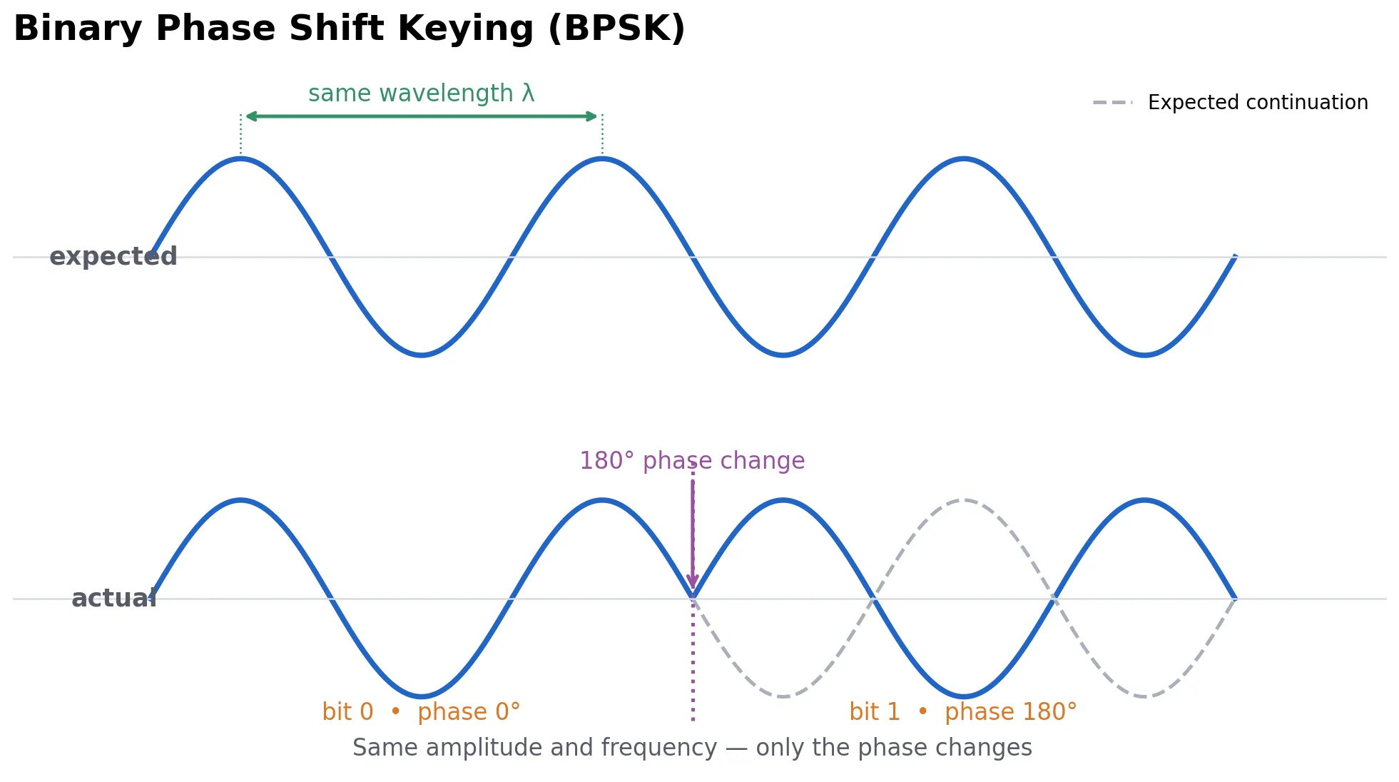
The frequency is still the same. But at a particular moment, we change the position of the wave within its cycle.
For example:
- 0 → phase 0°
- 1 → phase 180°
This is the basic idea behind BPSK — Binary Phase Shift Keying.
With phase modulation we have more variety. We can use the same idea but instead of only two possible phases, we can use four:
- 00 → 45°
- 01 → 135°
- 10 → 225°
- 11 → 315°
Now one transmitted symbol carries 2 bits. This is QPSK — Quadrature Phase Shift Keying.
Both BPSK and QPSK are used extensively in Wi-Fi when robustness is more important than raw data rate. We will explore this more deeply in later articles. For now, the aim is to illustrate phase modulation.
QAM—change the amplitude and phase
Another modulation scheme that is very relevant to Wi-Fi is QAM—Quadrature Amplitude Modulation. Instead of changing only the phase or only the amplitude, we can change both.
This is a more advanced technique. To understand it, let’s represent the same signal in this form:
This is called the I/Q representation. It describes the same wave as the earlier formula because
We can therefore interpret the signal as a sum of two orthogonal components and .
Now, let’s assume that . This gives four different pairs—, , , and —called constellation points, which we can use to encode information.
These combinations all result in and .
With that we can see that 4-QAM is the same as QPSK.
A more interesting case is , which gives us 16 different pairs.
Take a few constellation points:
Same phase, different amplitude.
But:
has and .
This is 16-QAM, in which both amplitude and phase vary. It encodes four bits per symbol.
There are also higher-order QAM schemes.
With 64 points:
64-QAM → 6 bits per symbolWith 256 points:
256-QAM → 8 bits per symbolWith 1024-QAM:
1024-QAM → 10 bits per symbolAnd Wi-Fi 7 can use 4096-QAM:
4096-QAM → 12 bits per symbolThe trade-off is fundamental: the more constellation points you have, the closer together they are. Noise and interference can then make the receiver confuse one point with another.
So, conceptually:
Poor signal ──────────────────────────────── Excellent signal

BPSK → QPSK → 16-QAM → 64-QAM → 256-QAM → 1024-QAM → 4096-QAM

robust                                        high throughput
few bits/symbol                              many bits/symbol
This is one of the reasons why moving closer to a Wi-Fi access point can increase your throughput dramatically even though your channel bandwidth hasn’t changed.